Sapcon Instrument
Leveraging on our strong vendor network and able professionals we are able to offer a qualitative range of Sapcon Instrument. The range offered by us is widely acclaimed for its niche quality and excellent performance. Capacitance Continuous Level Indicator, Trans lite Fuel Level Sensor, R.F. Admittance Level Switch, Vibrating Rod Level Switch are some of our renowned products. We test this range as per the leading industry standards. We offer:
Compact Admittance type Level Switch
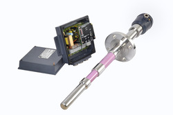
 SAPCON 'ADMiRE' is a high-end RISC core micro controller based level sensing limit switch, based on admittance principle. With it's specially developed algorithm it tracks the material trend continuously. In association with its 3-element probe utilizing the driven shield principle, it compensates for material build-up and thus it is immune to material build-up to a much larger extent. Simple push button type - hassle-free - calibration renders the unit installation and commissioning much easier. Fail safe selection and Cover/Uncover delays are settable any time while the device is in use. Available output options are PNP-NO and SPDT change-over relay. Power options are 10 to 55 VDC for PNP/NO and 85 to 265 VAC 50/60Hz for SPDT changeover type. SPDT with AC operation is also available in Flameproof enclosure.
Features:
• Easy to calibrate, using a push-button.
• Active build-up compensation algorithm - immunity against material build-up.
• Temperature stable circuitry - drift free reliable switching operation.
• Compact size and short insertion length, ideal for use in constricted places
• Low maintenance with no moving parts.
• Modular construction, so low down time.
• Driven shield system. Can tolerate certain amount of coating.
• Easy installation with switches and one bi-color LED.
• Selectable fail-safe condition (maximum/minimum)
• Configurable probe covered and/or uncovered delay.
• Fail safe PNP-NO output for DC and Changeover SPDT relay output for AC operation
System Description:
The sense and ground element of the probe form the electrodes of a capacitor with the service material as the dielectric. When the probe is not covered, the dielectric is that of air, whereas when covered, it is that of the service material. A change in the physical level of the material causes a change in the dielectric media between the two electrodes, thus causing a change in the measured capacitance. Using its three electrode sensing element, Ad Mire calculates the admittance of the capacitor being formed by the material. Ad Mire tracks the maximum and minimum values of the admittance change and thus tracks the status of material. If Ad Mire is operated in OPTIMIZATION mode, then it will give material by observing "material falling - admittance lowering" and "material rising - admittance increasing" trend, which will be guided by the calibration time set-point material to admittance relation. This continuous compensation will give correct switching output even when build-up is way too thick. When operated as normal level limit switch, it will give switching output as per above and below calibration time material to admittance setting.
Level Transmitter
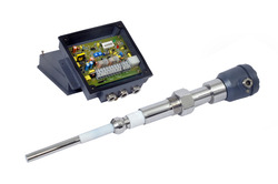
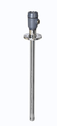
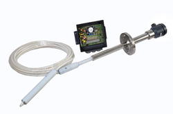
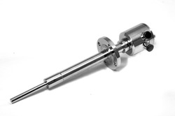
![]() The MPILC series is a microprocessor based level detection assembly designed to withstand the acute environment conditions and give you accurate detection of service material level in your process unit. This continuous level indicator can be used for any solid or liquid that has a homogenous composition and a stable dielectric value.
The MPILC series is a microprocessor based level detection assembly designed to withstand the acute environment conditions and give you accurate detection of service material level in your process unit. This continuous level indicator can be used for any solid or liquid that has a homogenous composition and a stable dielectric value.
The MPILC system has a microprocessor which checks the complete system and itself before validating the signal. A flashing green LED serves as heartbeat to indicate a healthy system. In the event of occurrence of a system fault such as incorrect wiring, open or short sensor connection, failure of probe insulation, improper grounding or electronic insert failure, the heartbeat stops, fault LED glows, display indicates “Err--“ and the relay contacts revert to their fail-safe condition.
The MPILC continuous level measurement system uses a two-wire Pulse Frequency Modulation (PFM) for interference-free signal transmission between probe and evaluation unit. Complete indication system is checked before each measurement. The system has an auto-compensation for temperature drift in the vicinity of the per-amplifier.
Technical Data:
| Housing | Cast Aluminum Whether-proof Staving Enamel painted, suitable for back,panel/wall mounting. |
| Cable Entries | 3 Nos. ½” BSP/NPT |
| Operating Temperature | –20 to +60º C |
| Mains | 90 -260 V AC / 50 - 60 Hz. 24V DC |
| Power Consumption | 3.5 VA approx. |
| Measuring range | 10 pF to 4500 pF |
| Offset | 30 pF to 280pF |
| Indication | Percentage display from – 50% to +150% on multipurpose 5 Digit 0.5” LED display (2” display also available in separate housing) |
| Accuracy | +/- 2% of the measuring range |
| Programming | via 5 push button keys |
| Analog Output | 4 -20 mA galvanic isolated output with two wire capability |
| Load Resistance | RL (Max) = 1 KΩ |
| Galvanic Isolated | 18 to 22 V (Safe RL (Max) = 800 Ω for on board supply |
| Relay output | 3 potential free relays, (rated at 6A,230V,AC, 50Hz for non-inductive load), for three point level switching Independent/pump control switching. Time delay programmable up to 99 sec. |
| Dimensions | Overall 185X185X85 mm |
PRE-AMPLIFIER (Electronic Insert) LDC - 117:
| Housing | Plastic with electronics potted epoxy resin, mounted in probe head. |
| Potting | -20º C to 80º C. 12 V at 17 mA max. derived from evaluation unit only. |
| Operating Temperature | -20º C to +80º C |
| Supply | 18V DC at 10mA (approx) derived from evaluation unit |
| Measuring Frequency | 50 -250 KHz |
Probe:
| Probe Head | Cast Al. weather-proof. |
| Mounting | Flange or Screwed as per requirement |
| Length | 150 mm to 3000 mm in Rod Probe, greater than 3000 mm in Rope |
| Insulation | Part or Full PVC, PTFE, Ceramic (Part Only) depending on service temperature of 80º C, 200º C or 400º C respectively. |
RF Admittance Level Switch
 We hold instrumental expertise in offering our valued patrons with an excellent range of R.F. Admittance Level Switch. It is manufactured in tandem with leading industry standards in desired specifications and makes to meet different work requirement. This range is widely appreciated for its low power consumption and longer service life. Our clients can avail this range at market leading prices.
Features:
• Ergonomically designed
• Low power consumption
• Excellent make
Technical Data:
| Housing | Cast Aluminum, weather proof, back panel / wall mounting. |
| Cable Entries | 3 No. / 2 No. |
| Max. Amb. Temp. | -20º C to + 60º C. |
| Power Consumption | 5 VA approx. |
| Mains Voltage | 230 V or 110 V AC (-15% to +10%), 50 Hz; 24 V AC/DC 90 to 260 V AC universal power supply (to be specified while ordering). |
| Relay Output | One/two set (s) of potential free change over contacts rated at 230V AC 6A, 50 Hz for non-inductive loads. |
| Fail-Safe Mode | Max. or Min. field selectable. |
| Indication (switching) | Red LED for alarm, Green LED for normal. |
| Indication (sensitivity) | 10 step LED dot / bar display |
| Response Time | 0.2 second typical. |
| Switching Delay | Adjustable from 0.5 to 20 second for probe covered or uncovered. |
| Connection to Probe | Via co-axial screened cable with drain wire. |
| Switching Hysteresis | 0.2 pF. typical. |
Solid Level Measurement Switch
 Technical Data:
| Housing | Cast Aluminum, weather proof, back panel (wall mounting) / Integral. |
| Cable Entry | 3 No. / 2 No. |
| Max. Amb. Temp | -20º C to +60º C. |
| Power Consumption | 5 VA approx. |
| Mains Voltage | 230 V or 110 V AC (-15% to +10%), 50/60 Hz; 24 V AC/DC; 90 to 260 V AC universal power supply |
| Relay Output | One/two set (s) of potential free change over contacts rated at 230V AC 6A, 50 Hz for non-inductive load. |
| Fail Safe Mode | Max. or Min. field selectable. |
| Indication | Red LED for alarm, Green LED for normal. |
| Response Time | 2 to 5 second |
| Switching Delay for | Adjustable from 2 to 20 second for probe covered and un-covered condition. |
| Interconnection Cable | a) Remote version 2-core independent screen. b) Split version 3-core unscreened. |
| Standard Evaluation Unit | |
| Overall Dim. | 180 x 180 x 85 mm |
| Weight | 2.5 Kg. |
Model Selection SLM Series Fork Level Switch:
| Tuning Fork | Stainless steel 316 |
| Mounting | 1½” screwed or 2" flanged. |
| Frequency | 85 Hz Std. (approximately) |
| Vessel Temp. | -20º C to + 80º C. |
| Length | 150 to 3500 mm. |
| Extension | Pipe (Gl or SS). |
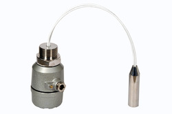
Elixir Liquid Level Switch
 Elixir liquid level Switch which consumes low power and can be used for liquids up to 10000 cP and is suitable up to temperature limits of 200°C. This single-point liquid indicator is extremely compact making it suitable for constricted places.
Elixir level switch uses the RISC Core micro-controller technology which makes it reliable & more accurate for level detection of any liquid or slurry (even highly viscous up to 10,000 cP). The instrument has an adjustable switching delay for covered and uncovered conditions. The electronics is integral with the fork and can be mounted in different ways such as top or side mounting. If the use is in hazardous area, you could choose the Flame proof version. You also have the flexibility of choosing the insertion length.
Elixir has no moving parts and is not affected by the turbulence in the tank, floating particles, suspensions or gas bubbles. This makes it a superior choice over the traditional float switches. If the liquid/slurry service material is very viscous, Elixir is the instrument of choice. The instrument neither requires adjustments nor is dependent on the position, thus making it the best option for liquid level switching in small tanks, pipes and mixing tanks.
Applications:
You can use Elixir for level detection of all types of liquids in storage tanks, mixing tanks and pipe lines having temperature up to 200°C and viscosity up to 10,000 cP and density greater than 0.7 gm/cc. Elixir is suitable for most of the applications, where traditional float switches were previously used and for liquids, which are sticky, corrosive, agitated, splashing and foaming.
Principle:
A specially shaped tuning fork is kept vibrating by piezoelectric elements at a set frequency. The frequency of the fork changes when the tines are immersed in the liquid. The change in the frequency is detected and used for switching a relay. The output contacts of the relay can in turn be used for annunciation or control.
Technical Data :
| Housing | Cast aluminum weather-proof and Flameproof suitable for mounting in hazardous area Gas group IIA & IIB as per IS-2148 |
| Cable Entries | 2 Nos. |
| Mains | 19 to 260 V AC, 50/60 Hz & 11 to 55 VDC |
| Output | One set (1 SPDT) of potential free change over contacts rated at 6A 230V AC & 6A 25 VDC for non-inductive load. |
| Time Delay | Adjustable from 1 to 20 second for probe covered & uncovered condition. |
| Indication | Red LED for alarm and Green LED for normal condition. |
| Power Consumption | 5 VA approx. |
| Response Time | 1 second. approx. |
| Operating Temp. | -20ºC to +60ºC |
| Fail-Safe Mode | High or Low field selectable. |
Probe:
| Tuning Fork | Stainless steel 316 |
| Mounting | 1" or 1½" BSP screwed (flanged mounting on request). 1½" BSP for high temperature version. |
| Extension | Stainless steel pipe. |
| Probe Length | Min. 128 mm, max. 3500 mm. |
| Operating | -20º C to + 80º C. |
| Temperature | Standard models (high temp. models up to 200º C are also available.) |
| Viscosity | Up to 10000 cP. |
| Density | Greater than 0.7 gm/cc. |
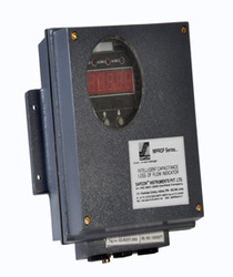
Loss of Head Indicator
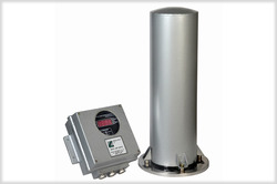
 Sapcon LOH (loss of head indicator) is a perfect solution of measuring differential level in open channels and is widely used in water treatment plants and filter stations.
Salient Features:
• Latest RISC core micro controller technology.
• Measured level is displayed continuously from -50% to 150%.
• Multipurpose 5 digit seven segment LED display for best resolution and better viewing from distance.
• Two wire pulse coded digital communication from sensor to evaluation unit.
• Supports as much as 1 km distance between sensor and evaluation unit with shielded two core cables.
• Galvanic ally isolated true two wire 4-20mA proportional to 0% and 100% level is available for remote indication purpose.
• Two wire implementation solves the malfunction problems that occurs with various PLC 4-20 input interfaces and thus better suits
• For higher end automation.
• 4-20mA loop can handle 700 Ohm loop resistance with internal isolated supply.
• Three independent potential free relays providing flexibility of selecting three independent switch points.
Principle of Operation:
The loop resistance can be 1K Ohm for External DC Supply of 24 Volts. In an application, the measuring electrode (sense probe) and the container wall (ground or reference probe) form a capacitor. The amount of capacitance of this capacitor is governed by the dielectric constant of the material between the two electrodes (sense probe & metallic container wall or reference probe or ground.
Technical Data:
| Housing | Cast Aluminum, Weather Proof, Staving Enamel Painted. Suitable for back panel / wall mounting. |
| Cable Entries | 3 Nos. of / BSP/NPT |
| Operating Ambient Temperature | -20°C to +60°C |
| Power supply | Universal Mains 90 to 265 VAC, 50/60Hz and 24VDC (@ 3 Watt) |
| Sensor to Evaluation Unit Cable | 2-Core; resistance per core not to exceed 30 Ohms. Use of shielded twisted pair cables is recommended for long runs of cable. Cable lengths of 1000 meters are thus supported with grounded cable shields. |
| Utilizable span | 10 to 4500 PF |
| Zero% Range | 30pf to 250pf |
| 100% Range | 10pf to 4500pf (Difference from Zero %) |
| Outputs | Current 4 to 20mA. 3 Potential Free relays with One set of Potential Free Change Over Contact per Relay. |
| Contact Ratings | 6 Amp @ 230VAC 50/60 Hz for non-inductive loads. |
| Indication Continuous | -50% to 150% digitally on 1 ” Seven Segment Display |
| Switching | 5 mm Red LEDs’ for Alarm Indication. |
| Switching Hysteresis | 1% in Single Point Switching, 1 to 98% selectable in Pump Control. |
Loss of Head indicator Fail Safe Select Set Point Select Weight Electronic Insert Housing Plastic Power Supply Measuring Frequency Operating Ambient Temperature Sensitivity Output
Specifications:
• Field Selectable through interactive relay configuration menu
• 2.3 Kg Approx.N
• - LDC117, LCDM 111
• potted with epoxy resin.
• 16VDC @ 5mA derived from Sensor Communication Interface of Evaluation Unit.
• 250Khz to 20Khz. Reverse Frequency Measurement.
• 20 C to +60.
Capacitance Continuous Level Indicator
 We extend a well-tested range of Capacitance Continuous Level Indicator to our valued patrons. This range is offered in different designs and specifications as detailed by the client. It comes in cast aluminum, weather proof enclosure. It also features a back pane so that it can be easily mounted on the wall. We offer this range in standard as well as customized designs to meet the varied requirements of our clients. This range is offered at very reasonable prices.
Features:
• Dimensionally accurate
• Fine finish
• Longer service life
Technical Data:
| Housing | Cast Aluminum, Weather proof, back panel/wall mounting |
| Cable Entry | 3 Nos. / 2 Nos. |
| Max. Amb. Temp. | -20 oC to + 60n oC. |
| Power Consumption | 5 VA approx. |
| Mains Voltage | 230 V or 110 V AC (-15% to +10%), 50 Hz; 24 V AC/DC; 90 to 260 V AC universal power supply. (to be specified while ordering). |
| Relay Output | One/two set (s) of potential free c/o contacts rated at 230V AC 6A, 50 Hz for non-inductive load per set point. |
| Fail-Safe Mode | Max. or Min. Field selectable. |
| Indication | Red LED for alarm, Green LED for normal, Yellow LED for system fault. |
| Response Time | 0.2 Second |
| Switching Delay for | Adjustable from 0.5 to 20 Second. for probe covered or uncovered condition. |
| Connection to Electronic Insert | 3 - core un sunscreen cable. |
| Initial Capacitance | 0 to 290 pf. in 3 overlapping ranges. (For single point switching) 0 to 1200 pf. in 3 overlapping ranges.(For pump control & multi point switching) |
| Switching Hysteresis | 0.5 pF. typical. (For independent switching) & Continuously adjustable over the entire range. (For pump control switching) |
Electronic Insert - LDC 311:
| Housing | Plastic, potted in epoxy resin. |
| Frequency | 500 kHz. (approximately). |
| Ambient Temp. | -20o C to 80o C. |
| Supply Voltage | 15 V derived from evaluation unit. |
| Output Signal | 3 to 12 V DC. |
Water Level Switch
 This Water Level Switch is conducive for liquids that have a conductivity of equal to or more than 25 m Siemens. The system is economical to install as no special cable is required for signal transmission. The level probe and the evaluation unit can be connected using a long cable. The AC is provided on the probe for preventing electrode deterioration.
Salient Features:
• Two point sensors for independent switching and automatic control of pump.
• Four point switching with two pump control logic.
• Three point switching: two for pump control logic and one independent point with or without a settable delay (for probe covered or uncovered).
• A variety of probes is available for your specific process.
Principle:
A low AC voltage is applied between the probe electrode and the tank wall (or reference electrode in case of insulated tank). When the water/liquid comes in contact with the electrode tip, a conductive path is established between the sense electrode and the tank wall/reference electrode. This current is sensed, amplified and made to operate a relay whose contacts in turn can be used for annunciation/control.
Technical Data:
| Housing | Cast aluminum, Weather-proof Staving enamel painted suitable for back panel/wall mounting. |
| Cable Entries | 3 Nos. of 1/2 “ BSP |
| Mains | 110 or 230 V AC (-15 to + 10%) 50 Hz (as specified in order). |
| Relay Output | One set of potential free change over contacts rated at 6A 230 V AC, 50Hz for non-inductive load. |
| Power Consumption | 5 VA approx. |
| Fail-Safe Mode | High or Low field selectable. |
| Response Time | 0.5 second |
| Switching Delay | 0.5 to 20 seconds for probe covered and uncovered condition |
| Maximum Sensitivity | 25 Micro Siemens |
| Operating mode | (A) Single point switching. (B) Two-point switching with pump control logic. |
| Indication | Red LED for Alarm, Green LED for Normal. |
| Mounting | 1½” BSP Screwed or Flanged mounting. |
| Operating Temp. | -20º C to + 60º C. |
| Weight | ~2 Kg. |
Level Probe:
| Voltage | 12 V AC (across probe & tank wall/ grounding electrode) |
| Current | <4 mA (between probe & tank wall/grounding electrode through liquid) |
| Operating Temp. | Up to 80º C (Standard model) Up to 200º C (Optional) |
ROF Level Sensor
 Technical Data:
| Housing | Cast aluminum, weather proof, staving enamel painted, suitable for back panel/wall mounting |
| Cable Entry | 3 Nos. ½” BSP / NPT |
| Tolerable ambient temp | -20°C to +60°C |
| Power supply | 90 to 260V AC 50Hz, and 24V DC |
| Power consumption | 3.5VA (approx.) |
| Utilizable span | 10 to 4500 PF |
| Zero setting range | 30 to 280 PF |
| Indication range | 50% to 150% on multipurpose 5 digit 0.5” LED |
| Accuracy | +/- 1% FSD |
| Switching Hysterisis | 1% in single point switching and 1 to 98% selectable in 2 point Pump control logic. |
| Programming interface | 5 Push Button Keys |
| Analog output | 4 to 20 ma galvanic ally isolated into Max 1K Ohm load for 24V DC user supply. Max 800 Ohm for internal isolated supply of 18 to 22 V DC. |
| Output | 3 sets of potential free change over contacts rated at 6A, 230V, AC, 50Hz for non-inductive loads |
| Switching delay | Programmable up to 99 sec. |
| Fail-safe | High/Low field programmable |
| Dimensions | 180 x 180 x 85 mm |
PRE-AMPLIFIER (electronic insert) LDC117:
| Housing | Plastic with electronics potted, mounted in Probe Head |
| Operating Temp. | - 20 to +80 deg. C |
| Supply | 18 V DC at 8ma (approx.) derived from evaluation unit |
| Measuring Frequency | 250Hz to 20 KHz reverse frequency measurement |
Admittance Level Switch
 The SLA M Series switch can be efficiently used to reduce the inventory as the same evaluation unit can be field configured either for High or Low level fail-safe detection. The SLA...M series Ignores build-up of service material between probe, the vessel walls and the coating. The level limit switch uses 3-Electrode technique with driven shield arrangement to achieve high degree of immunity.
The measuring system for this level limit detection tool consists of an evaluation unit and an immune-coat probe that could be mounted either from the top or side of the vessel. The probe comprises sense and shield electrodes electrically isolated from the metallic tank by means of suitable insulators. The sense electrode of the switch and the vessel wall serve as the two electrodes of a capacitor with the service material as the dielectric. A change in material level causes a change in dielectric, which in turn causes a change in admittance of this tank capacitor.
The processed signal is used to energize or DE-energize a relay whose output contacts are available for annunciation or control.
Probe:
A wide variety of probes with different mounting connections is available to suit various applications. We offer specially designed ceramic insulated rod / rope probe suitable for operating temperatures up to 6000 C max.
Technical Data:
| Housing | Cast Aluminum, weather proof, back panel / wall mounting. |
| Cable Entries | 3 No. / 2 No. |
| Max. Amb. Temp. | -20º C to + 60º C. |
| Power Consumption | 5 VA approx. |
| Mains Voltage | 230 V or 110 V AC (-15% to +10%), 50 Hz; 24 V AC/DC 90 to 260 V AC universal power supply (to be specified while ordering). |
| Relay Output | One/two set (s) of potential free change over contacts rated at 230V AC 6A, 50 Hz for non-inductive loads. |
| Fail-Safe Mode | Max. or Min. field selectable. |
| Indication (switching) | Red LED for alarm, Green LED for normal. |
| Indication (sensitivity) | 10 step LED dot / bar display |
| Response Time | 0.2 second typical. |
| Switching Delay | Adjustable from 0.5 to 20 second for probe covered or uncovered. |
| Connection to Probe | Via co-axial screened cable with drain wire. |
| Switching Hysteresis | 0.2 pF. typical. |
Intelligent Admittance Level Limit Switch
 Intelligent and Self Checking:
A microprocessor checks the complete system and itself before validating the signal. A flashing green LED serves as a heartbeat to indicate a healthy system In the event of occurrence of a system fault such as incorrect wiring, open or short sensor connection, failure of probe insulation, improper grounding or electronic insert failure, the heartbeat stops, fault LED glows, display indicates "E---" and the relay contacts revert to their fail-safe condition.
Highly Reliable:
Two-overbold (Ctrl+B)e Pulse Frequency Modulation (PFM) is used for interference-free signal transmission between probe and evaluation unit. Complete system is checked before each measurement. Auto compensation for temperature drift in the vicinity of per-amplifier.
Technical Data:
| Housing | Cast aluminum, Weather-proof, Staving enamel painted, suitable for back panel / wall mounting. |
| Cable Entry | 3 Nos. of ½” BSP /NPT /NG20 |
| Ambient Temperature | 20º C to + 60º C. |
| Mains | 110/230 V AC (-10 to +10%) 50 Hz (as specified in order). |
| Power Consumption | 5 VA approx. |
| Indication (Switching) | Red LED for each level alarm, red LED for fault alarm, flashing green LED as heart-beat for healthy condition. |
| Indication (calibration) | LCD, one digit for mode field and two digits for data field. |
| Response Time | 0.2 Second. Typical. |
| Switching Delay | Programmable upto 99 Second. For probe covered/ uncovered condition for each set point. |
| Connection to | 2-core ordinary cable, |
| Electronic Insert | having max. resistance of 25 W per core. |
| Initial capacitance | 20 to 1200 pF. |
| Switching Hysteresis | Approx. 0.5 pF at initial |
| (single point operation) | Capacitance of 30 pF. |
| Switching Hysteresis | Programmable over |
| (Two point pump control) | entire setting range. |
| Build-up Compensation | Approx. 0 - 99 steps |
| Relay Output | One set of potential free change over contacts per channel rated at 6A 230 V AC, 50Hz for non- inductive load. |
| Fail-Safe Mode | High or Low field programmable for both channels. |
| Weight | 2.5 Kgs approx. |
| Overall dimensions | 180 x 180 x 85 cm |
Electronic Insert:
| Housing | Plastic with electronics potted in epoxy resin. |
| Measuring Frequency | 20º C to 80º C. 12 V at 17 mA max. derived from evaluation unit only. |
Probes:
| Housing | Cast Aluminum, SS, FTP-coated, HDPE. |
| Mounting | Flanged or Screwed as per requirement. |
| Electrode Element | Special 3-element Probe Sense, Shield and Ground. |
| Length | 150 mm to 3000 mm in Rod, Greater than 3000 mm in Rope. |
| Insulation | Part or full PVC, PTFE, Ceramic (Part only) depending on service temperature of 80º C, 200º C or 400º C respectively. |
Speed O Tester
 SAPCON Speed O Tester is a versatile speed limit switch suitable for detecting an over speed or under speed condition of rotating, reciprocating or conveying equipment. It can also detect a missing object amongst a series of continuously moving objects at a constant speed, such as a missing bucket in a bucket elevator.
Salient Features:
• Easy to install and simple to calibrate.
• Accurate pulse interval evaluation by comparison with a stable internal time base.
• Over-speed/ Under-speed alarm, field selectable, with fail-safe relay operation.
• Built-in adjustable start up delay with interlocking provision allows the monitored device to accelerate before the speed is evaluated.
• Flashing LED in the per-amplifier indicates the moving target is within the sensing range and facilitates target to detector distance setting.
• Flashing LED in the evaluation unit confirms receipt of pulses.
• Normal, Alarm and Power Failure, indicated by LED's.
• Rugged motion detector probe especially designed for heavy industrial application.
Technical Data:
| Housing | Cast Aluminum, Weather Proof, Staving enamel painted, suitable for back/wall mounting. |
| Cable Entries | 3 Nos. of ½” BSP / NPT |
| Operating Temperature | 20º C to +60º C. |
| Mains | 110/230 V AC (-10 to +10%) 50Hz (as specified in order). |
| Power Consumption | 5 VA approx. |
| Relay Output | One set of potential free change over contacts rated at 6A, 230V AC 50Hz for non-inductive load. |
| Power to Pre-amplifier | 12V DC at 50 m A max. |
| Indication | Red/Green LED's for Alarm and Normal, Flashing Yellow LED for pulse/fault diagnosis. |
| Alarm Mode | Over-speed / Under-speed field selectable |
| Measuring Range | 2 to 3000 Pulses / Min. (PPM) |
| Set Point Adjustment | Coarse setting by jumpers, fine setting by potentiometer. |
| Start-Up Time Delay | 0 to 60 Second Adjustable by means of a potentiometer. |
| Interlock | By potential free NO contact of contractor controlling the Motor of the monitored equipment. |
| Overall Dimensions | 180 x 180 x 85 mm. |
PER-AMPLIFIER (Electronic Insert):
| Housing | Plastic with built-in terminals. |
| Potting | 20º C to 80º C. 12 V at 17 mA max. derived from evaluation unit only. |
| Operating Temperature | 20º C to + 80º C. |
| Supply | 12 V DC at 50 mA max. derived from Evaluation Unit. |
| Output | Current pulses. |
Probes:
| Probe Head | Cast Al. weather-proof. |
| Mounting | Cast Al. Flange. |
| Target Range Adjustment | By tri-clamp mechanism. |
| Max. Detection range | 100 mm |
| Target Material | Ferromagnetic |
| Min. Target Area | 20 x 20 cm |
| Temp. Range | 120º C (Standard) |
Microprocessor Based Level Switch
 We call this series the “Intelligent Capacitance Level switch series”. And we do so because MP-SLC has a microprocessor that checks the complete system (including itself) before validating a signal. You will see a flashing green LED that serves as heartbeat to indicate a healthy system. In the case of a system fault,which may result due to incorrect wiring, open or short sensor connection, inadequate probe insulation improper grounding or electronic insert failure, the heartbeat stops fault LED glows, display indicates “E---“ and the relay contacts revert to their fail-safe condition.
The MP-SLC level switch is a highly reliable liquid and solids level indicator. A two wire Pulse Frequency Modulation (PFM) is used for interference-free signal transmission between probe and evaluation unit. Complete system is checked before each measurement and the system has a provision for auto-compensation for temperature drift in the vicinity of a per-amplifier.
The MP-SLC series exhibits a high degree program ability. Important functions such as operating mode (independent/pump control), delayed switching for probe covered/uncovered conditions, fail safe high/low, switching sensitivity, switching delay and set point calibration are programmable via a keypad. You can store the programmed parameters in a non-volatile memory indefinitely requiring no battery backup.
Technical Data:
| Housing | Cast aluminum, Weather-proof Staving enamel painted, suitable for back panel/wall mounting. |
| Cable Entries | 3 Nos. of ½” BSP |
| Mains Voltage | 110 V or 230 V AC (-10 to +10%) 50 Hz (as specified in order). |
| Power Consumption | 5 VA approx. |
| Initial Capacitance Adjustment | 30 pF to 280 pF in two selectable ranges. |
| Indication | 2½ digit, 0.5 inch Red LED display; 2 inch display is also available in separate housing |
| Operating Temperature | -20o C to +60o C |
| Utilizable Capacitance Variation | 10 pF to 4500 pF in three selectable ranges. |
| Accuracy | ± 2% of the F.S.D. |
| Outputs | 0 -100% digital display 0/4 -20 mA into RL max. 400 Ohms and 0 -5 V DC for RL >25 KW for remote indicators and recorders. |
| Dimensions | 185 mm x 185 mm x 85 mm |
| Weight | 2.3 Kg (approx.) |
Electronic Insert - LCD 312:
| Housing | Plastic with electronics potted in epoxy resin. |
| Supply | 20 V DC max. 10 mA. derived from Evaluation Unit. |
| Measuring Frequency | 33 K Hz (approx.) |
| Operating Temperature | -20o C to + 60o C. |
Probe:
| Housing | Cast Aluminum, SS, FRP-coated, HDPE. |
| Mounting | Flanged or Screwed as per requirement. |
| Length | 150 mm to 3000 mm in Rod, Greater than 3000 mm in Rope. |
| Insulation | Part or full PVC, PTFE, Ceramic (Part only) depending on service temperature of 80oC, 200oC or 400oC respectively. |
Admittance Level Limit Switch SLA series
SLA series is an admittance based level switch series with RF signal transmission between probe and evaluation unit via a co-axial cable with drain wire having driven shield arrangement to eliminate cable capacitance and drift due to change of cable capacitance with temperature. You can install the evaluation unit even far from the probe. The calibration controls are available in the evaluation unit.
The SLA Series switch can be efficiently used to reduce the inventory as the same evaluation unit can be field configured either for High or Low level fail-safe detection. The SLA series Ignores build-up of service material between probe, the vessel walls and the coating. SLA uses 3-Electrode technique with driven shield arrangement to achieve high degree of immunity.
The measuring system for this level detection tool consists of an evaluation unit and an immune-coat probe that could be mounted either from the top or side of the vessel. The probe comprises sense and shield electrodes electrically isolated from the metallic tank by means of suitable insulators. The sense electrode of the switch and the vessel wall serve as the two electrodes of a capacitor with the service material as the dielectric. A change in material level causes a change in dielectric, which in turn causes a change in admittance of this tank capacitor.
Technical Data:
| Housing | Plastic, potted in epoxy resin. |
| Measuring Frequency | ~ 500 KHz. |
| Ambient Temp. | -20º C to + 80º C. |
| Supply Voltage | 15 V derived from evaluation unit. |
| Output Signal | 3 to 12 V DC. |
Evaluation Unit:
| Housing | Cast Aluminum, Weather proof, back panel/wall mounting |
| Cable Entries | 3 Nos. |
| Max. Amb. Temp. | - 20º C to + 60º C. |
| Power Consumption | 5 VA approx. |
| Mains Voltage | 230 V or 110 V AC (-15% to +10%), 50 Hz; 24 V AC/DC 90 to 260 V AC universal power supply (to be specified while ordering). |
| Relay Output | One/two sets of potential free change over contacts rated at 230V AC 6A, 50 Hz for non-inductive loads per set point. |
| Fail-Safe Mode | Max. or Min. Field selectable. Indication Red LED for alarm, Green LED for normal, Yellow LED for system fault. |
| Indication (switching) | Red LED for alarm, Green LED for normal. |
| Response Time | 0.2 Second |
| Switching Delay 322/622/ 822/922 | Adjustable from 0.5 to 20 Second. for probe covered or uncovered. |
| Connection to Probe Insert | 3 - core unscreened cable. |
| Initial Capacitance SLA 122/222 322/622/822 SLA 522/722/922 | 0 to 290 pf. in 3 overlapping ranges. 0 to 1200 pf. in 3 overlapping ranges. |
| Switching /Hysteresis SLA 122/222/ 322/622/822 SLA 522/722/922 | 0.5 pf. typical. Continuously adjustable over the entire range. |
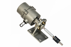
Translite Fuel Level Sensor
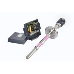
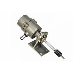
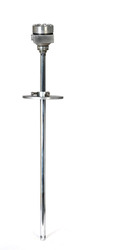
![]() Sapcon Instruments offers the Translite Fuel Level Sensor family of fuel level sensor instruments which use the capacitance technology for accurate fuel and oil level measurement in process plants. The Translite Fuel Level Sensor indicators have no moving parts and can be ideally used in extreme plant conditions of high temperature and pressure.
Sapcon Instruments offers the Translite Fuel Level Sensor family of fuel level sensor instruments which use the capacitance technology for accurate fuel and oil level measurement in process plants. The Translite Fuel Level Sensor indicators have no moving parts and can be ideally used in extreme plant conditions of high temperature and pressure.
The TRANSlite instrument range supports a power supply within DC automation is available from 11 to 55 VDC, addressing the need for 12V, 24V and 48V industrial supply options. 4-20mA Current Loop is galvanically isolated (4 Wire) and PLC, SCADA compatible. 4-20mA Current Loop can supply up to 1000 Ohm series load with 24VDC supply. This means 4-20mA signal can be carried to longer distance. The ease of calibration ensures user friendliness: “Just let it know the fuellevel for 4mA and 20mA, rest it will take care of.” Following are the options for you to choose from:
TRANSlite - It is composed of the specially developed Capacitance change gagging circuit. TRANSlite uses a fast RISC based processor which is the best in its class for evaluating fuel level using capacitance. The capacitance is formed by the sense rod and the metallic container wall. For non-metallic and/or non-uniform shaped containers, a metallic stilling well is provided. The amount of capacitance is proportional to the level of material between the sense rod and metallic wall of stilling container.
TRANS~lite - The best affordable liquid fuel level measuring solution for high temperature conditions. Its key feature is the ease of calibration which is not commonly available in this range of fuel level transmitters. TRANS~lite allows electronic-less measurement of level up-to 5 meters distance between the probe and the electronics.
TRANS2lite- is a micro controller based 2 wire capacitance fuel level sensor. TRANS2lite has temperature compensated electronics that provide a stable output. This fuel level sensor allows calibration in steps of 10% from 0 to 100% eliminating the need for rigorous emptying filling calibration.
Best in the Industry:
Fast delivery on request, cost effectiveness and low power consumption make this device cut above the rest. All in all, TRANSlite is a complete “value for your money” device and if your system has a SCADA or PLC interface, TRANSlite is your best buy.
Customization per your level measurement needs:
TRANSlite instruments can be custom designed to your specification requirements. The sensors have no moving parts and are extremely accurate. They can be designed to fit within the tightest of space envelopes and withstand the most acute work environments.
Vibrating Rod Level Switch
 Technical Data:
| Housing | Cast aluminum, weather-proof staving enamel painted, suitable for back panel/wall |
| Cable Entry | 3 No. / 2 No. |
| Mains | 110 or 230 V AC (-15% to +10% ) 50 Hz ; 240 V AC/DC; 90 to 260 V AC universal power supply. |
| Relay Output | One/two set (s) of potential free change over contacts rated at 6A 230V AC, 50Hz for non-inductive load. |
| Time Delay | Adjustable from 1 to 20 second for probe covered & uncovered condition. |
| Indication | Red LED for alarm and Green LED for normal condition. |
| Power Consumption | 5 VA approx. |
| Response Time | 1 second. approx. |
| Operating Temp. | -20ºC to +60ºC |
| Fail-Safe Mode | High or Low field selectable. |
Probe:
| Tuning Fork | Stainless steel 316 |
| Mounting | 1" or 1½" BSP screwed (flanged mounting on request). 1½" BSP for high temperature version. |
| Extension | Stainless steel pipe. |
| Probe Length | Min. 128 mm, max. 3500 mm. |
| Operating | -20º C to + 80º C. |
| Temperature | Standard models (high temp. models up to 200º C are also available.) |
| Viscosity | Up to 10000 cP. |
| Density | Greater than 0.7 gm/cc. |
Capacitance Level Switch
 The SLC series level limit switch can be used for detection of solids that are fine/coarse or in bulk. This level measurement switch can also be used for liquids including water. SLC series is also used with liquids that are sticky/non-sticky corrosive or non-corrosive for switching conveyors off, indicating empty tank condition, preventing pumps for running dry and for detecting the separation layers accurately.
The SLC series capacitance based level switch has been used by many of our clients successfully in the Cement, Plastic, Power, Food, Chemicals, Fertilizer, Sugar, Detergent and many other industries
SLC series consists of an evaluation unit, an electronic insert and the probe. The probe can be mounted form the top or side of the vessel. The probe system comprises a sense electrode which is insulated from the metallic tank by means of a suitable insulator. The sense electrode and the vessel wall serve as the two electrodes of a capacitor with the service material as the dielectric. A change in material level causes a change in the dielectric, which in turn causes the value of this tank capacitor to change.
An accurate measurement of this change causes an indirect measure of level of the material in the tank. The electronic insert measures the change of capacitance accurately by using Radio Frequency (R.F.) technique. The change is converted to a DC voltage variation, which is transmitted to the evaluation unit via a 3-core UN-screened cable for further processing. The processed signal is used to energize or DE-energize a relay whose output contacts are available for annunciation or control.
Salient Features:
You can calibrate the level limit evaluation unit far away from the probe. This level switch uses ordinary 3 core cable for interconnecting the electronic insert with the evaluation unit. A variety of built in multi-point evaluation units is available to reduce the number of discrete controllers thereby reducing the overall cost. The fail-safe high/low selection feature is available as a standard. This systems is economical to install and you can even have it in circular enclosures for your specific requirements.
Technical Data:
| Housing | Cast Aluminum, Weather proof, back panel/wall mounting |
| Cable Entries | 3 Nos. / 2 Nos. |
| Max. Amb. Temp. | - 20º C to + 60º C. |
| Power Consumption | 5 VA approx. |
| Mains Voltage | 230 V or 110 V AC (-15% to +10%), 50 Hz; 24 V AC/DC; 90 to 260 V AC universal power supply. (to be specified while ordering). |
| Relay Output | One/two sets of potential free change over contacts rated at 230V AC 6A, 50 Hz for non-inductive loads per set point. |
| Fail-Safe Mode | Max. or Min. Field selectable. |
| Indication | Red LED for alarm, Green LED for normal, Yellow LED for system fault. |
| Response Time | 0.2 Second |
| Switching Delay | Adjustable from 0.5 to 20 Second. for probe covered or uncovered condition. |
| Connection to Electronic Insert | 3 - core UN-screened cable. |
| Initial Capacitance | 0 to 290 pf. in 3 overlapping ranges. (For single point switching) 0 to 1200 pf. in 3 overlapping ranges. (For pump control & multi point switching) |
| Switching Hysteresis | 0.5 pF. typical. (For independent switching) & Continuously adjustable over the entire range. (For pump control switching) |
Vibrating Rod Level Switch
 The Sapcon Vibrating Rod level switch "Vibrosonde" (SLP Series) is a tuning based switch for single point control. The instrument has an adjustable switching delay for covered and uncovered conditions. The electronics is integral with the fork and can be mounted in different ways such as wall/back panel mounting or remote mounting. If the use is in hazardous area, you could choose the flame proof version. You also have the flexibility of choosing the insertion length.
he Vibrosonde (SLP Series) is single cylindrical vibrating rod with no adjustment, no moving parts, no affected by moisture contents and electrical properties of process material.
Applications:
High and Low level limit control of free flowing powders and granules such as cement, flour, detergent, plastic granules.
Where is it used:
Vibrosonde (SLP… series) level switches are successfully used in processing plants for High and Low level limit control of free flowing powders and granules such as cement, flour, detergent, plastic granules.
Principle:
A specially shaped tuning rod is kept vibrating by piezo-electric elements. The frequency of the fork changes when the tines are immersed in the liquid. The change in the frequency is detected and used for switching a relay. The output contacts of the relay can in turn be used for annunciation or control.
Technical Data:
| Housing | Cast aluminum, weather-proof staving enamel painted, suitable for back panel/wall |
| Cable Entry | 3 No. / 2 No. |
| Mains | 110 or 230 V AC (-15% to +10% ) 50 Hz ; 240 V AC/DC; 90 to 260 V AC universal power supply. |
| Relay Output | One/two set (s) of potential free change over contacts rated at 6A 230V AC, 50Hz for non-inductive load. |
| Time Delay | Adjustable from 1 to 20 second for probe covered & uncovered condition. |
| Indication | Red LED for alarm and Green LED for normal condition. |
| Power Consumption | 5 VA approx. |
| Response Time | 1 second. approx. |
| Operating Temp. | -20ºC to +60ºC |
| Fail-Safe Mode | High or Low field selectable. |
Probe:
| Tuning Fork | Stainless steel 316 |
| Mounting | 1" or 1½" BSP screwed (flanged mounting on request). 1½" BSP for high temperature version. |
| Extension | Stainless steel pipe. |
| Probe Length | Min. 128 mm, max. 3500 mm. |
| Operating | -20º C to + 80º C. |
| Temperature | Standard models (high temp. models up to 200º C are also available.) |
| Viscosity | Up to 10000 cP. |
| Density | Greater than 0.7 gm/cc. |
Continuous Level Indicator
 Dependability, strength, durability, ruggedness are the keywords when it comes to the use of level instruments for continuous monitoring in difficult environment conditions. The ILC... series stands up to the requirements of a tough continuous level detector and offers the following benefits:
• Level is displayed on a built-in Digital Panel Meter having 0.5 inch high digits for better visibility.
• Standard output signal of 0-5 V DC and 4-20 mA DC proportional to 0-100% level change available for remote indicators and recorders.
• "In Situ" range selection and calibration possible from evaluation unit. Probe head accessibility not required.
• Measuring system has no moving parts so does not suffer any mechanical wear and tear and hence is maintenance free.
• Economical to install, since ordinary 3-core cable is used for interconnection.
• Flame-proof probe suitable for hazardous areas as per IS-2148 for group IIA and IIB is available.
As far as the service material is concerned, the ILC indicator can be used with conductive or non-conductive liquids, powdered or grained materials of homogeneous composition having stable dielectric constant. Our clients in the Oil, Food, Water treatment, Diesel, Chemicals etc. industries have used the ILC level indicator to their satisfaction.
In the ILC...series the measuring electrode and container wall (or grounding probe) form a capacitor with the material serving as the dielectric. A change in material level in the container causes a change in capacitance. The electronic insert converts this change to a proportional DC which is transmitted via the interconnecting cable to the evaluation unit wherein the signal after processing is displayed digitally.
Technical Data:
| Housing | Cast Aluminium, Weather proof, back panel/wall mounting |
| Cable Entry | 3 Nos. / 2 Nos. |
| Max. Amb. Temp. | -20o C to + 60o C. |
| Power Consumption | 5 VA approx. |
| Mains Voltage | 230 V or 110 V AC (-15% to +10%), 50 Hz; 24 V AC/DC; 90 to 260 V AC universal power supply. (to be specified while ordering). |
| Relay Output | One/two set (s) of potential free c/o contacts rated at 230V AC 6A, 50 Hz for non-inductive load per set point. |
| Fail-Safe Mode | Max. or Min. Field selectable. |
| Indication | Red LED for alarm, Green LED for normal, Yellow LED for system fault. |
| Response Time | 0.2 Second |
| Switching Delay for | Adjustable from 0.5 to 20 Second. for probe covered or uncovered condition. |
| Connection to Electronic Insert | 3 - core unscreened cable. |
| Initial Capacitance | 0 to 290 pf. in 3 overlapping ranges. (For single point switching) 0 to 1200 pf. in 3 overlapping ranges.(For pump control & multi point switching) |
| Switching Hysteresis | 0.5 pF. typical. (For independent switching) & Continuously adjustable over the entire range. (For pump control switching) |
Electronic Insert - LDC 311:
| Housing | Plastic, potted in epoxy resin. |
| Frequency | 500 kHz. (approximately). |
| Ambient Temp. | -20o C to 80o C. |
| Supply Voltage | 15 V derived from evaluation unit. |
| Output Signal | 3 to 12 V DC. |
Solid Level Measurement Switch
This tuning fork level switch from Sapcon Instruments, known as the SLM series, is best suited for you if your operational unit involves level limit detection of:
• Fine grained free flowing solids including very low density and pneumatically conveyed media, powders, plastic chips, cement, sand, sugar, food grains
• For detecting level of granular solid material submerged in liquids of low viscosity, like sand, gravel, plastic chips under water.
• For applications requiring the processing of different type of material in the same vessel.
Features (SLM Series):
The SLM series tuning fork level detector has no moving parts and requires no calibration. The High/Low selection feature is available as a standard feature unlike the instruments from other manufacturers. The SLM level switch is insensitive to material build-up and isn't affected by the electrical properties of the service material. You can choose an enclosure depending on you process plant conditions.We have housing that prevents and protects it from explosive conditions, dusty areas and unpredictable weather conditions. What else, we also have a circular enclosure available if you need.
• Various standards of the mounting according to plant conditions
• High temperature versions up to 200°C without the necessity of elaborate cooling arrangements
• Flame proof versions for hazardous areas.
Longer probe length use pipe extension made of GI or SS as required. Integral Versions meant for high temperature operation are provided with a stand-off arrangement for keeping the electronics in a relatively cooler environment. Adjustable probe length type are provided with gland arrangement for making length adjustments.
Technical Data:
| Housing | Cast Aluminum, weather proof, back panel (wall mounting) / Integral. |
| Cable Entry | 3 No. / 2 No. |
| Max. Amb. Temp | -20º C to +60º C. |
| Power Consumption | 5 VA approx. |
| Mains Voltage | 230 V or 110 V AC (-15% to +10%), 50/60 Hz; 24 V AC/DC; 90 to 260 V AC universal power supply |
| Relay Output | One/two set (s) of potential free change over contacts rated at 230V AC 6A, 50 Hz for non-inductive load. |
| Fail Safe Mode | Max. or Min. field selectable. |
| Indication | Red LED for alarm, Green LED for normal. |
| Response Time | 2 to 5 second |
| Switching Delay for | Adjustable from 2 to 20 second for probe covered and un-covered condition. |
| Interconnection Cable | a)Remote version 2-core independent screen. b)Split version 3-core unscreened. |
| Standard Evaluation Unit | |
| Overall Dim. | 180 x 180 x 85 mm |
| Weight | 2.5 Kg. |
Model SelectionSLM Series:
| Tuning Fork | Stainless steel 316 |
| Mounting | 1½” screwed or 2" flanged. |
| Frequency | 85 Hz Std. (approximately) |
| Vessel Temp. | -20º C to + 80º C. |
| Length | 150 to 3500 mm. |
| Extension | Pipe (Gl or SS). |